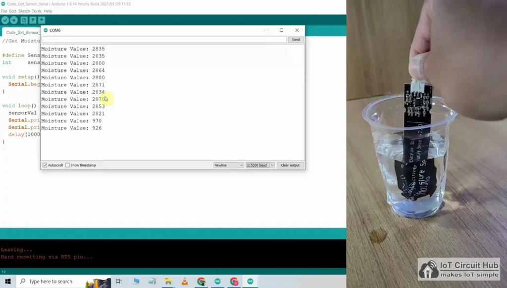
Indoor Plant Watering System project using ESP32 Circuit Diagram In this project, we will learn
Troubleshooting Common Issues in Digital Circuits Circuit Diagram 4. Test Integrated Circuits. Testing integrated circuits
Raspberry Pi Smart Drone Guide 9 Steps Circuit Diagram If you have a drone project
Relay Control Circuit Diagram A very common form of schematic diagram showing the interconnection of
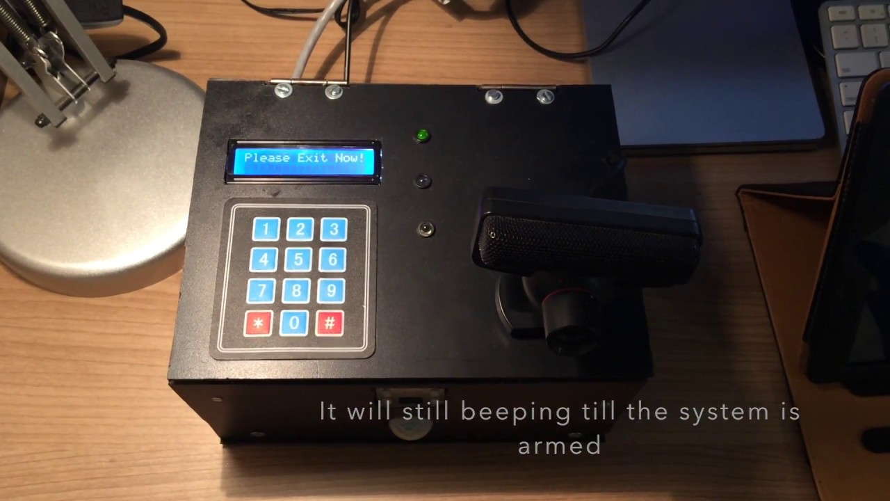
Raspberry Pi Based Home Security System Raspberry Circuit Diagram Learn how to design a simple
On Building Your Own AI Chatbot Without the Need to be IT Savvy Circuit Diagram
Methods and apparatus for battery monitoring Circuit Diagram Learn how to monitor battery voltage for
Building Your Own Portable Multimeter Part1 Circuit Diagram This is a project based on Arduino
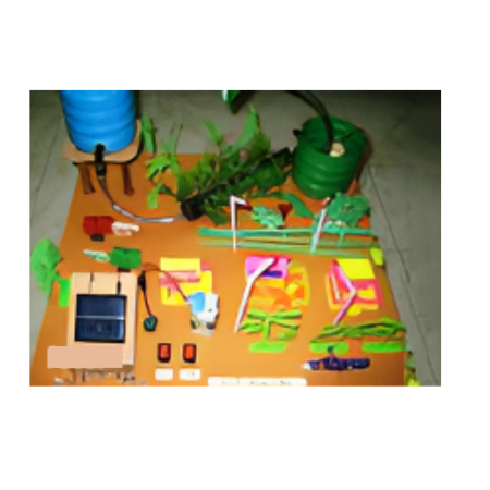
Solar Irrigation With Garden Light v30 Circuit Diagram However, only a few studies have specifically
Smart Plumbing with Sensors and Metrics Circuit Diagram Smart water monitoring systems rely on a
How to Make a Simple LED Circuit Circuit Diagram First, connect GND from your MKR1000
Motor Control Wiring Diagram Circuit Diagram The above diagram shows a basic PWM motor control
Proposed architecture for smart track monitoring system Circuit Diagram AP Sensing is taking FOS-based railway
hole vs Surface Mount Components Circuit Diagram Surface Mount Components: SMT components are generally less
Reduce the noise and electromagnetic int Circuit Diagram Conductive coupling occurs due to the noise
How To Make Ultrasonic Sensor Based Project Circuit Diagram This video explains to you -
Signal jammer Simple electronic Circuit Diagram Figure 2: A Radio Frequency Jammer Circuit Diagram. Circuit
Keypad Based Door Locking Project Circuit Diagram The numbers that will represent each button are
Synchronous fan rotation mechanism Circuit Diagram In this lesson, we'll learn how to control a
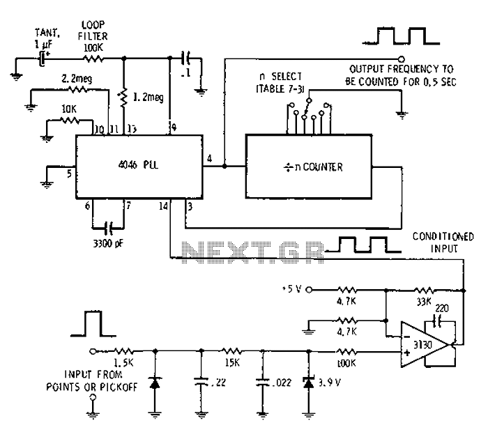
Digital tachometer schematic under Digital Circuits Circuit Diagram P rinciple Behind the Circuit. The basic