Membuat Smart Power Strip Dengan Arduino Circuit Diagram In this tutorial, we'll be using a 5V relay to switch the current to a power outlet on and off. We'll use the Arduino and a sensor to control when the relay switches. To learn more about the 5V relay and it's different modes of operation, see our article "How to Set Up a 5V Relay on the Arduino". We could always wire the relay directly to the device we want to control, but it's

The Internet of Things (IoT) has transformed the technological landscape, enabling the creation of smart devices and interconnected systems that enhance our daily lives and industrial processes. Arduino, a versatile and open-source electronics platform, is at the forefront of this revolution, providing a robust foundation for developing a wide In this paper, a device called the Smart Power-Strip is presented. It functions as a wall outlet adapter that is controlled by a microcontroller and can turn any standard home into an automated home without additional construction. It can obtain information by wi-fi connection or sensors then the microcontroller makes a decision based on the obtained information (e.g., programmed parameters
IoT Power Outlet with CircuitPython and Adafruit IO Circuit Diagram
I am looking for a smart power strip (European sockets) that I can: integrate with Home Assistant and control locally (i.e. no cloud) and control single outlets My smart home is built on WiFi and ZigBee, so the power strip should run on one or the other. This is a Smart WiFi based Power Strip I found on Amazon. I read in the comments section, that it can be flashed with Tasmota, but I have
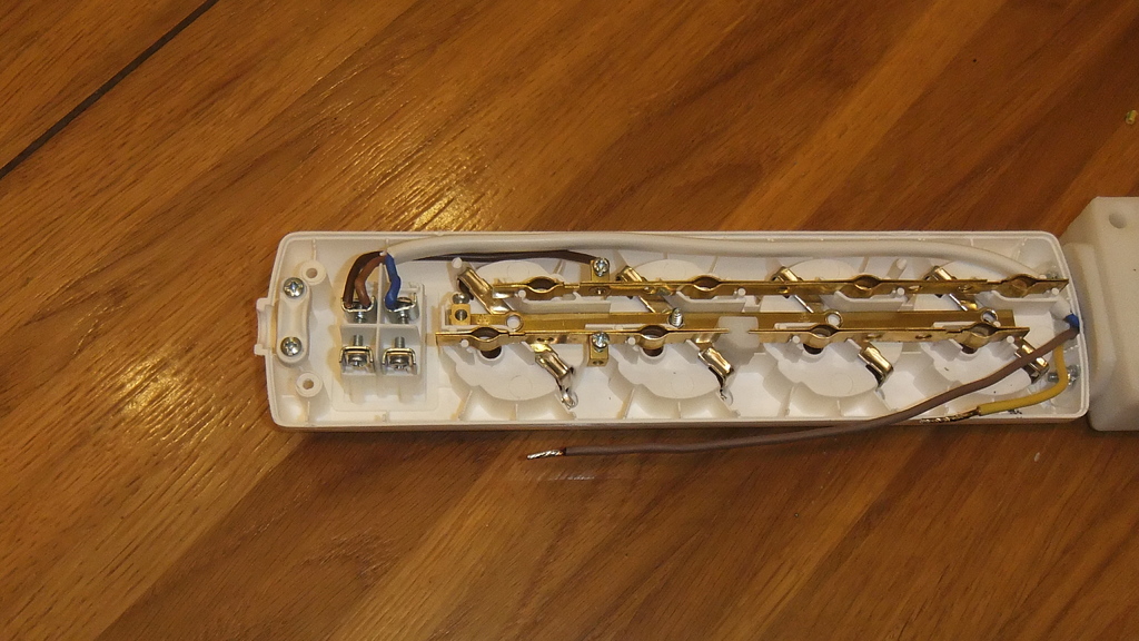
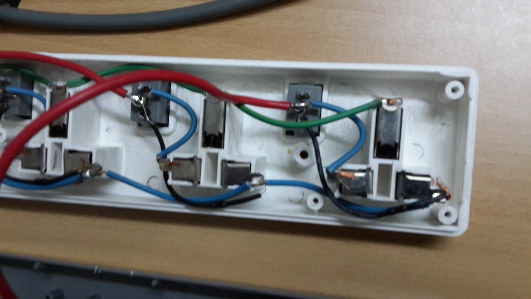
The Kicad files of the circuit can be found in the power_strip_kicad folder at. Step 4: Preparing the Power Strips. Modifying the power strips is pretty straight forward. As can be seen both the power strips have switches for each socket. The IoT power strip project also uses the same node-red and MQTT instances. Step 11: Suggestions for
Turn Any Appliance into a Smart Device with an Arduino Controlled Power ... Circuit Diagram
Figure 1 illustrates the simplified functional block diagram for the IoTtalk platform, which consists of the IoTtalk server (Figure 1 (a)), the IoT devices (Figure 1 (b) and (c)), and possibly a
