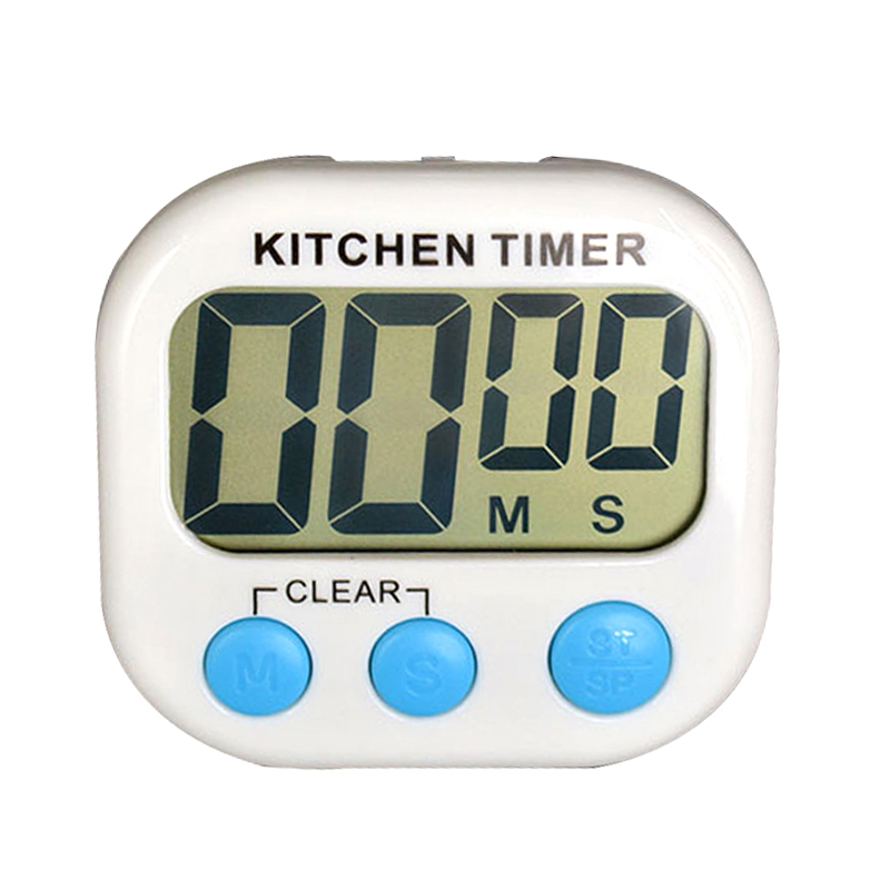
Simple Kitchen Timer Circuit Circuit Diagram This simple digital timer circuit can be used to obtain timing output through selectable ranges, which can be set from 0 to 99 second, with 1 second interval, 0 to 990 seconds with 10 second interval, and 0 to 99 minutes with 1 minute interval. All these timing outputs can be visualized and tracked through a 2 digit common anode LED display. This article discussed a simple connected kitchen timer build perfect for beginners and hobbyists starting with IoT projects. However, more experienced makers can add multiple other features that enhance the finished project, for example, a custom 3D-printed enclosure that houses the electronic components. This kitchen timer is simple enough, press and hold a button and it will count up it multiples of five minutes, until you release the button. Upon doing so the timer will flash, and begin counting down. This timer includes an alarm and a display, with a piercing piezo buzzer to get your attention.
In this tutorial we will see how to create a Timer start, UP/Down setting using push button and buzzer for Timer end with the Arduino board and the TM1637 displayComponents requiredArduino Nano - 1 noTM1637 module - 1 noPush Button switch - 3 no5V/3.3V Power module - 1 noBuzzer - 1 noCircuit diagramTM1637TM1637 seven segment modules is a ready made multiplexed seven segment display with 4 The simple digital timer circuit can obtain timing output through selectable ranges, such as 0 to 99 seconds, 0 to 990 seconds with 10 second intervals, and 0. Are; Can; How; What; The project involves building a digital kitchen timer with a knob, buzzer, and digital display using a 555 timer and a 14-stage binary counter. The system has Learn how to create a digital kitchen timer, complete with a knob, buzzer, and digital display. The system has two GreenPAK IC devices, one to keep time and the other to drive the display. The schematic is shown in Figure 1. A button is configured to start, pause, continue, and reset the timer. A maximum of 1 hour (or 59 minutes) can be
How to Build a Digital Kitchen Timer Using GreenPAK Circuit Diagram
This project steps through how to create a digital kitchen timers, complete with a knob, buzzer and a digital display. The system has two GreenPAK™ IC devices, one to keep time and the other to drive the display. The schematic is shown in Figure 1. A button is configured to start, pause, continue and reset the timer.

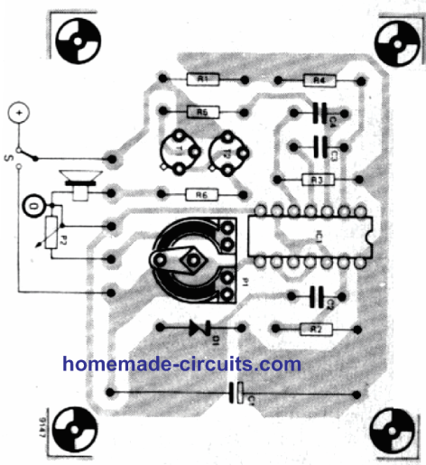
It uses a 555 timer integrated circuit configured as an astable mode with frequency that can be changed by changing the values of VR1 and capacitor C1. The circuit uses a 12V DC power supply with the capacitor value of 0.1uF for a timer duration of less than 10 minutes. If longer timer of up to 100 minutes is required, use a 1uF electrolytic